Paul Henneberry
Well-known member
Howdee,
I have recently completed my first three scratch built ukes (http://forum.ukuleleunderground.com/showthread.php?93820-The-heaviest-saprano-ever) and I thought I might share some information about the probably over the top jigs and tools that I made as the need arose during the project. In all cases I started by mining the wealth of knowledge that had already been freely shared through this forum but in most cases I came up with my own method of producing the jigs. The tools and materials that I had available usually played a big part in the method that I came up with.
I have already covered how I made radius dishes
http://forum.ukuleleunderground.com/showthread.php?94298-a-new-way-of-making-a-radius-dish
And how I cut fret slots
http://forum.ukuleleunderground.com/showthread.php?94388-fret-slot-cutting-with-a-circular-saw
So moving right along: routing rebates for binding and purfling:
For those of you who are new to the wonderful world of uke making and who are maybe wondering why this step is so complicated it is usual to bend the uke back and soundboard into a curve or hemisphere. Some makers go a bit tighter but I built these ukes with a 15’ radius back and a 25’ radius soundboard. This has acoustic benefits but it means that even the small flat base of a laminate trimmer could rock and cut at a strange angle if sat on the curve so you need some way of isolating the router from the curve while still cutting a rebate with a depth referenced to the surface and there are plenty of threads about the approach that I adopted already on the UU.
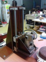
There isn’t anything revolutionary about this jig apart from maybe the linear bearings. For those not familiar with this technology they are not a bronze bush or anything so primitive. They are a ball bearing race designed to slide axially along a polished steel shaft. I can’t think of a good way of describing the mechanism apart from to say that the shaft is supported at all times on about 60 tiny steel balls and that these balls run in a race. There are maybe 150 of these balls running in 5 races. Long and the short, for our purposes there is no play and almost no friction when you mount them in a group of 4 as shown on the jig. The shafts are 16mm and the tower is made from 6mm and 8mm phenolic sheet. I purchased the shafts, bearings and standoffs from an Australian ebay retailer for about $100. The friction is so low that I quickly realised that I needed a counter weight. The total weight of the trimmer and carriage was about 2 kg and I thought that was a bit high over the small contact area where the rub block contacts the uke sound board or back so the counter weight is about 1.5kg. I had a 3 wing 25mm diameter rebate router bit and I turned up a series of sleaved bearings to produce the different rebates for the purfling and binding.
With this type of jig and operation you usually see some method of holding the body and levelling the surface that is being routed. I didn’t go to that much trouble for these ukes although I will next time. As seen in the photo I decided to keep the sides vertical by capturing the body in a shallow mold which was fine when routing the soundboard where the sides are perpendicular to the surface. Aware that the back is tapered I thought that the floating action of the router would ride with the height which it did. The slight problem is that the bit is cutting on a leading or trailing edge when routing the waist area which makes for some strange geometry resulting in a slightly not flat bottom rebate. Not a big problem (which a scrapper cleaned up) but I will be levelling both the SB and back next time. The accuracy and crispness of the rebate was excellent without any tear out on any of the woods I was cutting into. The Makita 3701 laminate trimmer is a great trimmer but it lacks a fine depth adjustment which is something I will have to work on. The first photo is a bit of a mock up after the event and if you look closely you will see that I have started gluing the fibre lines in.
I’m posting this information about the techniques that I came up not with to be critical of other methods or say that this is better but only to get people to consider developing their own methods based on what they have available or feel comfortable with.
Cheers
Paul
I have recently completed my first three scratch built ukes (http://forum.ukuleleunderground.com/showthread.php?93820-The-heaviest-saprano-ever) and I thought I might share some information about the probably over the top jigs and tools that I made as the need arose during the project. In all cases I started by mining the wealth of knowledge that had already been freely shared through this forum but in most cases I came up with my own method of producing the jigs. The tools and materials that I had available usually played a big part in the method that I came up with.
I have already covered how I made radius dishes
http://forum.ukuleleunderground.com/showthread.php?94298-a-new-way-of-making-a-radius-dish
And how I cut fret slots
http://forum.ukuleleunderground.com/showthread.php?94388-fret-slot-cutting-with-a-circular-saw
So moving right along: routing rebates for binding and purfling:
For those of you who are new to the wonderful world of uke making and who are maybe wondering why this step is so complicated it is usual to bend the uke back and soundboard into a curve or hemisphere. Some makers go a bit tighter but I built these ukes with a 15’ radius back and a 25’ radius soundboard. This has acoustic benefits but it means that even the small flat base of a laminate trimmer could rock and cut at a strange angle if sat on the curve so you need some way of isolating the router from the curve while still cutting a rebate with a depth referenced to the surface and there are plenty of threads about the approach that I adopted already on the UU.
There isn’t anything revolutionary about this jig apart from maybe the linear bearings. For those not familiar with this technology they are not a bronze bush or anything so primitive. They are a ball bearing race designed to slide axially along a polished steel shaft. I can’t think of a good way of describing the mechanism apart from to say that the shaft is supported at all times on about 60 tiny steel balls and that these balls run in a race. There are maybe 150 of these balls running in 5 races. Long and the short, for our purposes there is no play and almost no friction when you mount them in a group of 4 as shown on the jig. The shafts are 16mm and the tower is made from 6mm and 8mm phenolic sheet. I purchased the shafts, bearings and standoffs from an Australian ebay retailer for about $100. The friction is so low that I quickly realised that I needed a counter weight. The total weight of the trimmer and carriage was about 2 kg and I thought that was a bit high over the small contact area where the rub block contacts the uke sound board or back so the counter weight is about 1.5kg. I had a 3 wing 25mm diameter rebate router bit and I turned up a series of sleaved bearings to produce the different rebates for the purfling and binding.
With this type of jig and operation you usually see some method of holding the body and levelling the surface that is being routed. I didn’t go to that much trouble for these ukes although I will next time. As seen in the photo I decided to keep the sides vertical by capturing the body in a shallow mold which was fine when routing the soundboard where the sides are perpendicular to the surface. Aware that the back is tapered I thought that the floating action of the router would ride with the height which it did. The slight problem is that the bit is cutting on a leading or trailing edge when routing the waist area which makes for some strange geometry resulting in a slightly not flat bottom rebate. Not a big problem (which a scrapper cleaned up) but I will be levelling both the SB and back next time. The accuracy and crispness of the rebate was excellent without any tear out on any of the woods I was cutting into. The Makita 3701 laminate trimmer is a great trimmer but it lacks a fine depth adjustment which is something I will have to work on. The first photo is a bit of a mock up after the event and if you look closely you will see that I have started gluing the fibre lines in.
I’m posting this information about the techniques that I came up not with to be critical of other methods or say that this is better but only to get people to consider developing their own methods based on what they have available or feel comfortable with.
Cheers
Paul
Attachments


Last edited:


